
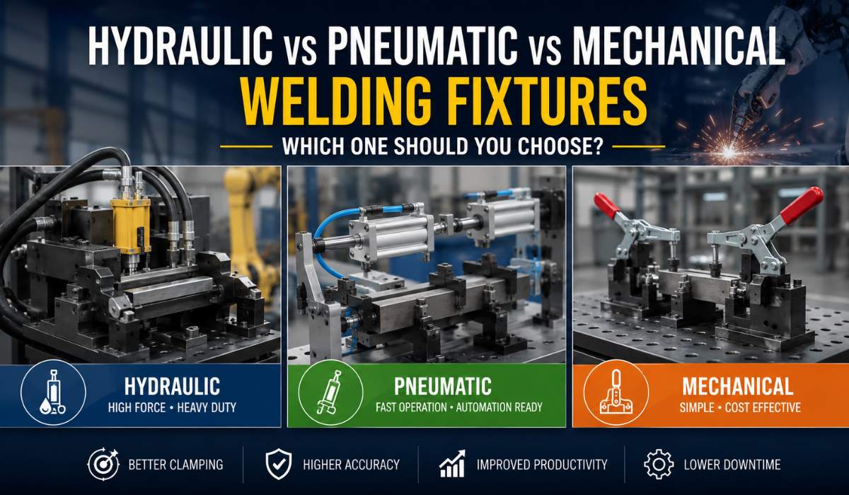
Every robotic welding cell is only as accurate as the fixture holding the part. And every fixture design starts with one decision that gets surprisingly little attention: how should the part actually be clamped? Hydraulic, pneumatic, and mechanical clamping each solve the holding problem differently — and choosing the wrong one is one of the most common reasons weld quality issues trace back to the fixture rather than the robot or the welder.
Table of Contents
- Why Clamping Method Matters More Than Most Buyers Realize
- Mechanical Clamping — How It Works
- Pneumatic Clamping — How It Works
- Hydraulic Clamping — How It Works
- Side-by-Side Comparison
- Cost Comparison in India
- How to Choose the Right Clamping Method
- Common Mistakes in Clamping Selection
- FAQs
Note for WordPress: link each TOC item to its corresponding heading anchor. Use a plugin or anchor block — written as plain numbered text here so the sequence stays 1 through 9 when pasted into the block editor.
Why Clamping Method Matters More Than Most Buyers Realize
When manufacturers evaluate fixture design for a new welding application, most of the conversation focuses on the locating scheme — where the part sits and how it’s positioned. The clamping method that actually holds the part in place during welding gets decided almost as an afterthought, often defaulting to whatever the fixture shop has used before.
This is a mistake. The clamping method determines how consistently the part is held cycle after cycle, how fast the fixture can be loaded and unloaded, how much force can be applied without distorting thin sheet metal, and how the fixture will perform after two years of continuous production. Each of the three main clamping technologies — mechanical, pneumatic, and hydraulic — has genuine strengths, and the right choice depends entirely on your specific application, not on habit.
Mechanical Clamping — How It Works
Mechanical clamping uses manually operated toggle clamps, screw clamps, or cam-lock mechanisms to hold the part. The operator physically engages the clamp — pulling a toggle lever, turning a screw, or rotating a cam — to apply and release clamping force.
This is the simplest and most common clamping method for low to medium volume production and for manual welding stations. It requires no compressed air or hydraulic power supply, has minimal moving parts to maintain, and is the lowest-cost option to implement. The trade-off is clamping force consistency — it depends on the operator engaging the clamp fully and consistently every cycle, and very high clamping forces are physically difficult for an operator to apply manually.
Mechanical clamping works well where cycle time is not critical, clamping force requirements are moderate, and the operation is manual or semi-automatic rather than fully robotic.
Pneumatic Clamping — How It Works
Pneumatic clamping uses compressed air to drive cylinders that apply clamping force. A solenoid valve, triggered automatically or by an operator button, directs air pressure to extend or retract the clamp. This makes pneumatic clamping fast — typical clamp cycle times are under one second — and easy to integrate with PLC controls for automatic sequencing in a robotic cell.
Pneumatic systems are widely used in robotic welding cells because they integrate cleanly with the cell’s control logic and provide fast, repeatable clamping force. The main limitation is maximum force — pneumatic cylinders are limited by air line pressure, typically 6 to 8 bar in Indian factory compressed air systems, which caps the practical clamping force compared to hydraulic systems. For thin sheet metal and small to medium components, this is rarely a constraint. For heavy fabrication or components requiring very high clamping force to resist welding distortion, it can be.
Hydraulic Clamping — How It Works
Hydraulic clamping uses pressurized hydraulic fluid, typically at 70 to 200 bar, to drive clamping cylinders. This delivers significantly higher clamping force than pneumatic systems in a comparable cylinder size — often 5 to 10 times the force for the same cylinder bore.
Hydraulic clamping is the standard choice for heavy fabrication, large components, and applications where high and consistent clamping force is essential to prevent part movement or distortion during welding. It is also commonly combined with multi-point clamping circuits, where a single hydraulic power unit drives multiple clamps simultaneously through a manifold — useful for complex parts with several clamping points that must engage in a specific sequence. This is the clamping method most often specified for SPM applications involving heavy components or high-force pressing operations.
The trade-off is system complexity and cost — hydraulic systems require a power unit, fluid reservoir, filtration, and more maintenance than pneumatic or mechanical systems, along with the housekeeping needed to manage hydraulic fluid in a clean manufacturing environment.
Side-by-Side Comparison
| Factor | Mechanical | Pneumatic | Hydraulic |
|---|---|---|---|
| Clamping Force | Low to medium — operator dependent | Medium — limited by air pressure (6-8 bar) | High — 70-200 bar, 5-10x pneumatic force |
| Speed | Slow — manual operation | Fast — under 1 second cycle | Fast — comparable to pneumatic |
| Automation Integration | Poor — requires manual operation | Excellent — standard for robotic cells | Good — requires power unit integration |
| Initial Cost | Lowest | Moderate | Highest |
| Maintenance | Minimal | Low — seals, air quality | Higher — fluid, filtration, power unit |
| Best For | Low volume, manual stations | Robotic cells, sheet metal, medium force | Heavy fabrication, high-force, multi-point clamping |
| Space Requirement | Minimal | Requires air supply line | Requires power unit — more floor space |
Cost Comparison in India
| Clamping System Type | Typical Cost Range (INR) | What’s Included |
|---|---|---|
| Mechanical toggle/cam clamps (per fixture) | ₹15,000 – ₹80,000 | Clamps, mounting hardware, basic locating elements |
| Pneumatic clamping system (per fixture) | ₹60,000 – ₹3 Lakh | Cylinders, valves, air manifold, basic PLC integration |
| Hydraulic clamping system (per fixture) | ₹1.5 Lakh – ₹8 Lakh | Cylinders, power unit, manifold, fluid system, controls |
| Multi-point hydraulic system (complex fixture) | ₹5 Lakh – ₹20 Lakh+ | Multiple synchronized clamps, shared power unit, sequencing controls |
These figures cover the clamping system only — not the full fixture base, locating elements, or robotic systems integration cost. For a complete welding cell budget including fixture, robot, and clamping system together, refer to our guide on robotic welding system cost in India.
How to Choose the Right Clamping Method
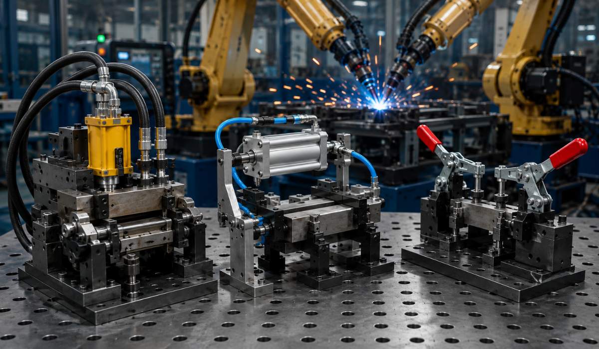
- Start with your required clamping force — calculate the force needed to hold the part against welding heat distortion and robot torch contact forces. If pneumatic pressure cannot deliver this reliably, hydraulic is the answer regardless of cost preference.
- Consider your cycle time target — pneumatic and hydraulic both clamp in under a second; mechanical clamping adds 5-15 seconds of manual operator time per cycle, which matters significantly at high volume.
- Evaluate part sensitivity — thin sheet metal parts can be damaged by excessive or uneven clamping force; pneumatic systems are easier to tune to lower, more controlled force levels than hydraulic.
- Account for multi-point clamping needs — if your part requires 4 or more clamps engaging in a specific sequence, hydraulic manifold systems handle this more reliably than independent pneumatic cylinders.
- Factor in your maintenance capability — hydraulic systems need more active maintenance (fluid checks, filtration, seal wear) than pneumatic or mechanical systems; confirm your maintenance team can support this before committing.
For most robotic two-wheeler frame welding and automotive bracket applications using sheet metal in the 1.5mm to 4mm range, pneumatic clamping is the standard choice. For heavy fabrication, chassis components, or thick-plate welding, hydraulic clamping is typically necessary.
Common Mistakes in Clamping Selection
- Defaulting to pneumatic for every application without checking if the force requirement actually needs hydraulic — leads to part movement and weld defects under load
- Over-specifying hydraulic for light sheet metal work — adds unnecessary cost and floor space for force the application never needed
- Not accounting for clamp sequencing in multi-point fixtures — clamps engaging in the wrong order can distort thin parts before welding even begins
- Ignoring duty cycle when selecting pneumatic components — components rated for occasional use will wear out quickly in continuous multi-shift production
- Underestimating hydraulic system footprint — power units, reservoirs, and plumbing need real floor space that’s often not accounted for in early layout planning
How PARC Robotics Approaches Clamping System Design
At PARC Robotics, clamping method selection is part of our fixture design process from the start — driven by part geometry, material thickness, required clamping force, and cycle time, not by defaulting to whichever system was used on the last project. We design and build fixtures using mechanical, pneumatic, and hydraulic clamping depending on what each specific application genuinely requires, and our quotes for SPM manufacturing cost projects always specify which clamping technology is included and why.
We have implemented all three clamping technologies across automotive frame, bracket, and welding positioner-integrated fixtures for clients across India since 2016.
Frequently Asked Questions
Which is better — hydraulic or pneumatic clamping for welding fixtures?
Neither is universally better — pneumatic clamping is faster to integrate and sufficient for most sheet metal and medium-force applications, while hydraulic clamping delivers significantly higher force and is better suited for heavy fabrication and multi-point clamping systems. The right choice depends on required clamping force and part sensitivity.
Can mechanical clamps be used in a robotic welding cell?
Mechanical clamps can be used in robotic cells but require manual operator engagement, which adds cycle time and reduces the automation benefit. Pneumatic or hydraulic clamping is generally preferred for fully automated robotic welding cells because they can be triggered automatically as part of the robot program.
How much clamping force does a welding fixture typically need?
Required clamping force depends on part thickness, material, and weld type, but typical automotive sheet metal applications need clamping forces in the range of 200 to 2,000 Newtons per clamp point, while heavy fabrication can require significantly higher force, often justifying hydraulic clamping.
What is the cost difference between pneumatic and hydraulic clamping systems?
A pneumatic clamping system for a typical fixture costs roughly ₹60,000 to ₹3 lakh, while an equivalent hydraulic clamping system costs roughly ₹1.5 lakh to ₹8 lakh due to the power unit, fluid system, and higher-spec components required.
Do hydraulic clamping systems require more maintenance than pneumatic?
Yes. Hydraulic systems require regular fluid checks, filtration maintenance, and seal inspection. Pneumatic systems require simpler maintenance focused mainly on air quality and seal wear, making them generally lower-maintenance than hydraulic systems.
Need Help Choosing the Right Clamping System for Your Fixture?
Share your part drawing, material thickness, and production volume with our engineering team. PARC Robotics will assess your clamping force requirements and recommend whether mechanical, pneumatic, or hydraulic clamping — or a combination — is right for your application, as part of your overall robotic welding cell design.
Typical response time — Within 24 working hours